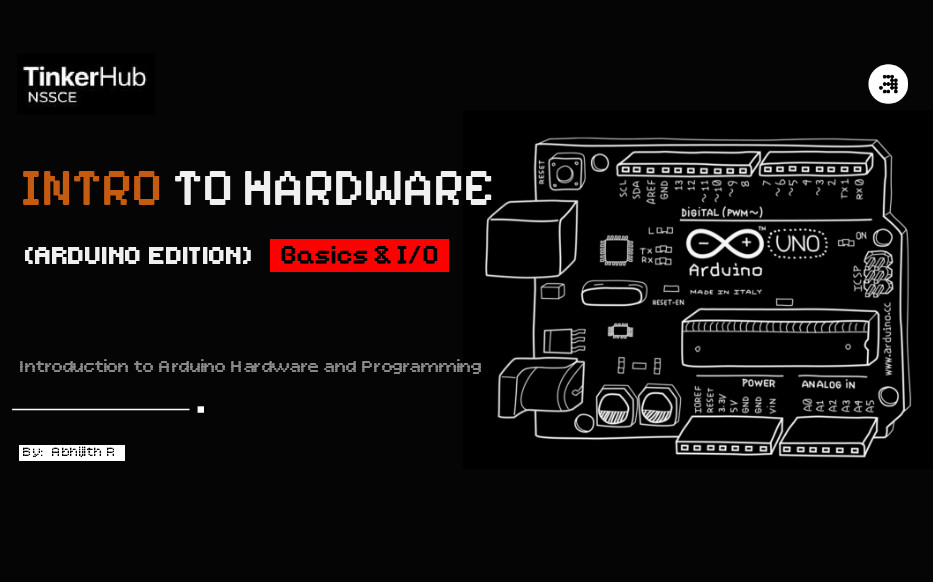
Intro to Hardware
Abstract
This module focuses on the fundamentals of Arduino microcontroller programming, digital Input/Output (I/O), and Pulse Width Modulation (PWM). By the culmination of this session, students will utilize these concepts to construct functional circuits, including a sequence-timed traffic light.
Download the Introduction to Hardware Presentation (PDF)
Target Audience: This guide assumes foundational knowledge of basic electronics, circuitry, and breadboarding. While these prerequisites are already understood by the audience, introductory electrical theory and breadboard schematics are included throughout this document as supplementary reference material.
Required Components
| Item | Quantity | Notes |
|---|---|---|
| Arduino Uno (or compatible) | 1 | Microcontroller board |
| USB cable | 1 | Communication interface |
| Breadboard | 1 | Half-size or full-size prototype board |
| LEDs (red, yellow, green) | 1 each | Standard 5mm Light Emitting Diodes |
| 220 Ω resistors | 3 | Color code: red-red-brown-gold |
| Pushbutton | 1 | Standard tactile switch |
| Jumper wires | ~10 | Male-to-male connection wires |
| Arduino IDE | - | Download link |
Note on Simulation: For students without physical hardware, refer to Section 8: Simulation Tools to model and execute all circuits virtually.
Contents
1. Theoretical Foundations (Reference)
The following fundamental electrical properties and calculations are provided as a quick reference.
| Term | Definition | Standard Unit |
|---|---|---|
| Voltage (V) | The electrical potential difference driving charge through a circuit. | Volts (V) |
| Current (I) | The rate of flow of electric charge. | Amperes (A) |
| Resistance (R) | The opposition to current flow within a conductor or component. | Ohms (Ω) |
Fluid Analogy: Voltage is analogous to water pressure, current to the volumetric flow rate, and resistance to the constriction of a pipe. Increased resistance proportionally reduces current for a constant voltage.
The relationship between these properties is defined by Ohm’s Law:
V = I × RApplication to LEDs: A Light Emitting Diode (LED) possesses minimal internal resistance. If connected directly to a 5V source, it will draw excessive current and undergo thermal failure. A resistor placed in series limits the current to operational parameters.
Calculating Current-Limiting Resistor Values: A standard red LED typically requires a forward voltage of ~2V and operates efficiently at 15-20 mA (0.015-0.020 A).
R = (Supply Voltage - LED Forward Voltage) / Desired CurrentR = (5V - 2V) / 0.015AR ≈ 200 Ω (Standard commercially available value: 220 Ω)Consequently, all LED circuits in this module incorporate a 220 Ω series resistor.
2. Anatomy of an Arduino Program
An Arduino program, conventionally referred to as a sketch, mandates the implementation of two primary structural functions:
// Executes once upon initialization or resetvoid setup() {  // Initialization parameters}
// Executes continuously following setup completionvoid loop() {  // Primary operational logic}
Execution Flow Diagram:
flowchart TD
    A["Power Initialization / Hardware Reset"] --> B["setup() Execution - Singular"]
    B --> C["loop() Initiation"]
    C --> D["Sequential Execution of loop() Instructions"]
    D --> C
The setup() function is utilized for hardware configuration, such as defining pin modes. The loop() function contains the primary execution logic, which iterates indefinitely at the microcontroller’s clock speed.
3. Digital Output
Principles of Digital Output
A digital output pin functions as a programmable switch, constrained to two discrete binary states:
- HIGH (5V logic level)
- LOW (0V logic level)
Digital pins actuate external components such as LEDs, relays, buzzers, and motor drivers.
Prototyping Board (Breadboard) Architecture
A breadboard facilitates solderless circuit prototyping. Internal conductive clips connect the insertion points (holes) in specific patterns.
flowchart LR
    subgraph Power_Rails ["Power Distribution Rails (Horizontal Connectivity)"]
        direction LR
        P1["+"] --- P2["+"] --- P3["+"]
        N1["-"] --- N2["-"] --- N3["-"]
    end

    subgraph Terminal_Strips ["Terminal Strips (Vertical Row Connectivity)"]
        direction LR
        Left["Row 1: a-b-c-d-e"] --- Gap{Isolation Trench} --- Right["Row 1: f-g-h-i-j"]
        Left2["Row 2: a-b-c-d-e"] --- Gap2{Isolation Trench} --- Right2["Row 2: f-g-h-i-j"]
    end
Implementation Note: Component leads must bridge separate rows to establish a circuit. Inserting both leads into the same row will create a short circuit.
LED Circuit Implementation
When interfacing an LED, a current-limiting resistor is strictly required.
flowchart LR
    A["Arduino Digital Pin 8"] -->|Control Signal| R["220 Ω Resistor"]
    R -->|Limited Current| L_Anode("LED Anode (+)<br/>Extended lead")
    L_Anode --> L_Cathode("LED Cathode (-)<br/>Truncated lead")
    L_Cathode --> GND["System Ground (GND)"]
Note: LEDs exhibit polarity. The anode must connect toward the positive potential (signal pin), and the cathode toward ground. Incorrect orientation prevents conduction.
Standard Library Functions
pinMode()
Configures the specified pin to behave either as an input or an output. This declaration occurs within the setup() block.
pinMode(8, OUTPUT); // Configures Pin 8 for signal transmissiondigitalWrite()
Assigns a HIGH or LOW state to a digital pin.
digitalWrite(8, HIGH); // Engages 5V potentialdigitalWrite(8, LOW); // Dissipates to 0Vdelay()
Suspends processor execution for a specified duration, defined in milliseconds. No subsequent instructions execute during this period.
delay(1000); // Suspends execution for 1000 milliseconds (1.0 seconds)State Oscillation Implementation (Blink)
int ledPin = 8; // Variable declaration for pin assignment
void setup() {  pinMode(ledPin, OUTPUT);}
void loop() {  digitalWrite(ledPin, HIGH); // Illuminate LED  delay(1000);                // Maintain state for 1 second  digitalWrite(ledPin, LOW);  // Extinguish LED  delay(1000);                // Maintain state for 1 second}
Variable Declaration
Variables allocate memory for data storage. Utilizing named variables enhances code readability and parameter modification efficiency.
int ledPin = 8; // Integer declarationbool isOn = true; // Boolean declarationlong delayTime = 500; // Extended integer declarationTask 1: Blink Implementation
Estimated Duration: ~15 minutes
- Construct the LED circuit adhering to the schematic (Pin 8 -> Resistor -> LED -> GND).
- Initialize the Arduino IDE and input the provided source code.
- Configure the target board and port interface via the Tools menu.
- Compile and deploy the software via Upload.
- Verify an oscillation frequency of 0.5 Hz (1 second HIGH, 1 second LOW).
Advanced Exercises:
- Modify the duty cycle to increase the oscillation frequency by a factor of two.
- Implement an SOS distress pattern sequence manually, omitting iterative loops.
4. Sequential Timing Systems (Traffic Light)
Varying temporal states establishes functional sequences. A traffic management system relies on sequential digitalWrite and delay executions to enforce state transitions.
stateDiagram-v2
    [*] --> Red
    Red --> Green: Transition at t=3s
    Green --> Yellow: Transition at t=3s
    Yellow --> Red: Transition at t=1s
Schematic Diagram:
flowchart LR
    P8["Digital Pin 8"] --> R1["220Ω Resistor"] --> L1(("Red LED")) --> GND["Ground Rail"]
    P9["Digital Pin 9"] --> R2["220Ω Resistor"] --> L2(("Yellow LED")) --> GND
    P10["Digital Pin 10"] --> R3["220Ω Resistor"] --> L3(("Green LED")) --> GND
Implementation Architecture:
int red = 8, yellow = 9, green = 10;
void setup() {  pinMode(red, OUTPUT);  pinMode(yellow, OUTPUT);  pinMode(green, OUTPUT);}
void loop() {  // Implement state transitions:  // Red HIGH -> Delay -> Red LOW -> Green HIGH -> Delay...}
Solution Reference
int red = 8, yellow = 9, green = 10;
void setup() {  pinMode(red, OUTPUT);  pinMode(yellow, OUTPUT);  pinMode(green, OUTPUT);}
void loop() {  digitalWrite(red, HIGH);  delay(3000);  digitalWrite(red, LOW);
  digitalWrite(green, HIGH);  delay(3000);  digitalWrite(green, LOW);
  digitalWrite(yellow, HIGH);  delay(1000);  digitalWrite(yellow, LOW);}
Students are encouraged to attempt the implementation independently before reviewing the provided solution.
Task 2: Traffic Light Implementation
Estimated Duration: ~20 minutes
- Integrate three independent LED circuits utilizing 220Ω resistors.
- Program the sequence corresponding to standard traffic light transitions.
- Implement the timing parameters: Red (3s), Green (3s), Yellow (1s).
- Deploy the code and verify continuous cyclic operation.
Advanced Exercise:
- Implement a precautionary “blinking yellow” state preceding the transition to red.
Knowledge Verification
Why does an LED necessitate a current-limiting resistor, whereas integrated modules (e.g., relays) generally do not?
An LED is a standard semiconductor diode lacking significant internal resistance; consequently, it cannot regulate current draw and will experience catastrophic failure if unmitigated. Integrated modules inherently contain onboard protection and current-limiting circuitry, negating the requirement for external series resistors.
5. Digital Input
Principles of Digital Input
In input mode, the microcontroller analyzes external signal logic levels. A digital input pin registers a boolean state (HIGH or LOW) based on applied voltage. Applications include tactile switches, proximity sensors, and digital interfaces.
Switch Circuit Implementation
flowchart LR
    PULLUP["Internal Pull-up Resistor<br>(Tied to 5V)"] -.- Node(("Junction"))
    P2["Digital Pin 2"] --- Node
    Node --- B["Momentary Switch"]
    B --- GND["GND"]
- The switch bridges across the isolation trench of the breadboard.
- One terminal connects to the target digital pin.
- The opposing terminal connects to systemic ground (GND).
- Note: An external pull-up resistor is omitted in favor of the microcontroller’s internal hardware.
Internal Pull-Up Resistors
Issue: An unconnected (“floating”) input terminal is highly susceptible to electromagnetic interference, resulting in stochastic state fluctuations rather than a defined boolean value.
Resolution: The INPUT_PULLUP parameter engages an internal resistor linked to the 5V rail, ensuring the pin defaults to a stable logic HIGH state.
Logic Inversion: Consequently, the unactuated state reads HIGH, while actuation forces a connection to ground, reading LOW.
pinMode(2, INPUT_PULLUP);flowchart LR
A["Switch Unactuated"] --> B["Logic Level: HIGH"]
C["Switch Actuated"] --> D["Logic Level: LOW"]
Function: digitalRead()
Evaluates and returns the instantaneous logic state of a specified pin.
int state = digitalRead(2);if (state == LOW) { // Actuation detected}Integrated Input/Output Implementation
int buttonPin = 2;int ledPin = 8;
void setup() {  pinMode(buttonPin, INPUT_PULLUP);  pinMode(ledPin, OUTPUT);}
void loop() {  int state = digitalRead(buttonPin);  if (state == LOW) {    digitalWrite(ledPin, HIGH); // Switch actuated; engage LED  } else {    digitalWrite(ledPin, LOW);  // Switch unactuated; disengage LED  }}
Task 3: Switch-Actuated Output
Estimated Duration: ~15 minutes
- Construct the switch circuit on digital pin 2 connecting to ground.
- Retain the LED circuit on digital pin 8.
- Compile and deploy the integrated I/O code.
- Verify that LED illumination corresponds strictly to switch actuation.
Advanced Exercise:
- Modify the logic to implement a state toggle (i.e., sequential presses alternate the LED state between ON and OFF). Hint: Requires state retention variables and edge-detection logic to prevent continuous toggling during prolonged actuation.
Knowledge Verification
What systemic behavior is expected if the INPUT_PULLUP parameter is omitted and the pin remains floating?
The LED will exhibit high-frequency oscillation and erratic behavior. The floating pin lacks a reference voltage and will interpret ambient electromagnetic noise as rapid alternations between HIGH and LOW logic states.
6. Pulse Width Modulation (PWM)
Principles of PWM
Standard digital pins provide discrete binary output. Pulse Width Modulation (PWM) simulates analog variance by rapidly oscillating the binary state. The duty cycle represents the percentage of time the signal remains in the HIGH state within a given period.
flowchart LR
    subgraph D25 [25% Duty Cycle - Low Intensity]
        direction LR
        D25_1[HIGH] -.-> D25_2[LOW] -.-> D25_3[LOW] -.-> D25_4[LOW]
        style D25_1 fill:#ff9999,stroke:#333,stroke-width:2px
        style D25_2 fill:#eee,stroke:#333
        style D25_3 fill:#eee,stroke:#333
        style D25_4 fill:#eee,stroke:#333
    end
    subgraph D50 [50% Duty Cycle - Medium Intensity]
        direction LR
        D50_1[HIGH] -.-> D50_2[HIGH] -.-> D50_3[LOW] -.-> D50_4[LOW]
        style D50_1 fill:#ff6666,stroke:#333,stroke-width:2px
        style D50_2 fill:#ff6666,stroke:#333,stroke-width:2px
        style D50_3 fill:#eee,stroke:#333
        style D50_4 fill:#eee,stroke:#333
    end
    subgraph D75 [75% Duty Cycle - High Intensity]
        direction LR
        D75_1[HIGH] -.-> D75_2[HIGH] -.-> D75_3[HIGH] -.-> D75_4[LOW]
        style D75_1 fill:#ff0000,stroke:#333,stroke-width:2px
        style D75_2 fill:#ff0000,stroke:#333,stroke-width:2px
        style D75_3 fill:#ff0000,stroke:#333,stroke-width:2px
        style D75_4 fill:#eee,stroke:#333
    end
This oscillation occurs at a frequency exceeding human visual perception (~490 Hz or 980 Hz), resulting in the optical illusion of variable luminance.
PWM Characteristics:
- Represents an average voltage rather than a true continuous analog waveform.
- Arduino Uno supports hardware PWM exclusively on pins denoted by the
~prefix (Pins 3, 5, 6, 9, 10, 11).
Function: analogWrite()
Modulates the duty cycle of a specified PWM-capable pin.
analogWrite(9, 128); // Value range: 0 (0% duty cycle) to 255 (100% duty cycle)Variable Intensity Implementation
Utilize the standard LED circuit interfaced with a PWM-compatible pin (e.g., Pin 9).
int brightness = 0;
void setup() {  pinMode(9, OUTPUT);}
void loop() {  analogWrite(9, brightness);  brightness = brightness + 5;
  if (brightness > 255) {    brightness = 0;  }
  delay(30); // 30-millisecond execution suspension}
Task 4: PWM Implementation
Estimated Duration: ~15 minutes
- Reallocate the LED control circuit to a PWM-capable pin.
- Compile and deploy the variable intensity program.
- Verify a linear increase in luminosity followed by a discrete reset to zero.
Advanced Exercise:
- Modify the logic to implement a bidirectional, continuous fade algorithm (triangular waveform) utilizing a directional state variable.
Knowledge Verification
Why does the provided algorithm exhibit a discontinuous reset rather than a gradual decline in intensity?
The variable brightness is strictly incremented. The conditional boundary check if (brightness > 255) reinitializes the variable to zero instantaneously. A continuous fade requires a state flag to dictate whether the loop should execute an increment or decrement operation based on the boundary conditions.
7. Extended Implementation Projects
Select one of the following architectural exercises for further application of the core concepts.
System 1: Interactive Illumination (Night Lamp)
- Integrate the PWM fade algorithm with digital input control.
- Actuation of the switch initiates system operation.
- Implement an extended fade coefficient for gradual illumination.
Solution Reference
int buttonPin = 2;int ledPin = 9; // PWM capable pinint brightness = 0;
void setup() {  pinMode(buttonPin, INPUT_PULLUP);  pinMode(ledPin, OUTPUT);}
void loop() {  if (digitalRead(buttonPin) == LOW) {    if (brightness < 255) {      brightness += 5;      delay(30);    }  } else {    if (brightness > 0) {      brightness -= 5;      delay(30);    }  }  analogWrite(ledPin, brightness);}
System 2: Programmatic Signaling (Morse Code)
- Design sequential logic utilizing defined temporal delays to transmit characters.
- Short duration (dot): ~200 ms; Long duration (dash): ~600 ms.
- Encode a specific string value (e.g., “HI”).
Standard Morse Code Mapping:
| Letter | Code | Letter | Code | Letter | Code |
|---|---|---|---|---|---|
| A | .- | J | .--- | S | ... |
| B | -... | K | -.- | T | - |
| C | -.-. | L | .-.. | U | ..- |
| D | -.. | M | -- | V | ...- |
| E | . | N | -. | W | .-- |
| F | ..-. | O | --- | X | -..- |
| G | --. | P | .--. | Y | -.-- |
| H | .... | Q | --.- | Z | --.. |
| I | .. | R | .-. |
Example output for “HI”: .... .. (four short pulses, interval, two short pulses)
Solution Reference
int ledPin = 8;int dotDelay = 200;int dashDelay = 600;
void setup() {  pinMode(ledPin, OUTPUT);}
void dot() {  digitalWrite(ledPin, HIGH);  delay(dotDelay);  digitalWrite(ledPin, LOW);  delay(dotDelay); // space between parts of the same letter}
void dash() {  digitalWrite(ledPin, HIGH);  delay(dashDelay);  digitalWrite(ledPin, LOW);  delay(dotDelay); // space between parts of the same letter}
void loop() {  // Transmit "H" (....)  dot(); dot(); dot(); dot();  delay(dashDelay); // Letter gap
  // Transmit "I" (..)  dot(); dot();  delay(2000); // Word gap}
System 3: Chronometric Evaluation (Reaction Timer)
This project requires outputting diagnostic data (the reaction time) from the Arduino back to your computer. This is achieved using the Serial Interface.
Serial Communication Basics
The microcontroller communicates with the computer via the USB cable using the Serial protocol. To view this data, you use the Serial Monitor (accessible via the magnifying glass icon in the top right of the Arduino IDE).
Serial.begin(9600);— Must be called insetup()to initialize communication at a specific baud rate (9600 bits per second is standard).Serial.print("Time: ");— Transmits text or variable data to the computer without a line break.Serial.println(timeElapsed);— Transmits data followed by a carriage return (moves to the next line).
flowchart TD
    A["Generate stochastic delay parameter"] --> B["Engage visual stimulus (LED HIGH)"]
    B --> C["Initiate chronometer"]
    C --> D["Monitor for interrupt (Switch Actuation)"]
    D --> E["Calculate temporal delta"]
    E --> F["Transmit data via Serial interface"]
Solution Reference
int buttonPin = 2;int ledPin = 8;unsigned long startTime;bool waitingForReaction = false;
void setup() {  pinMode(buttonPin, INPUT_PULLUP);  pinMode(ledPin, OUTPUT);  Serial.begin(9600);  randomSeed(analogRead(0)); // Seed random generator with unconnected pin}
void loop() {  if (!waitingForReaction) {    long randomDelay = random(2000, 6000); // Wait 2-6 seconds    delay(randomDelay);
    digitalWrite(ledPin, HIGH);    startTime = millis();    waitingForReaction = true;  }
  if (waitingForReaction && digitalRead(buttonPin) == LOW) {    unsigned long reactionTime = millis() - startTime;    digitalWrite(ledPin, LOW);
    Serial.print("Reaction Time: ");    Serial.print(reactionTime);    Serial.println(" ms");
    waitingForReaction = false;    delay(2000); // Pause before next round  }}
8. Simulation Tools
For development and verification without physical hardware, the following browser-based environments provide accurate hardware modeling and execution capability.
| Platform | Core Utility | Documentation URI |
|---|---|---|
| Tinkercad Circuits | Introductory schematic rendering and basic Arduino emulation. | tinkercad.com/circuits |
| Wokwi | High-fidelity hardware emulation, advanced IDE integration, and state-sharing features. | wokwi.com |
| SimulIDE | Desktop-based, offline analog and digital simulation architecture. | simulide.com |
| Falstad Circuit Simulator | Pure analog physics emulation (voltage vectors, current flow analysis). | falstad.com/circuit |
Methodological Recommendation: Prototyping code and schematics within a virtual environment (e.g., Wokwi) prior to physical deployment minimizes syntax and hardware diagnostic overhead.
9. Reference Material
- Core Arduino Language Specification
- Digital I/O: pinMode()
- Digital I/O: digitalWrite()
- Digital I/O: digitalRead()
- Analog I/O: analogWrite()
- Time: delay()
- Arduino IDE Repository
10. Hardware Diagnostic Matrix
| Observation | Probable Root Cause |
|---|---|
| LED fails to illuminate | Polarity inversion (anode/cathode reversed) or incomplete ground continuity. |
| Diminished LED luminosity | Incorrect pin assignment in software versus physical hardware mapping. |
| IDE compilation/upload failure | Incorrect COM port or board architecture selected in the deployment interface. |
| Switch registers continuous actuation | Omission of INPUT_PULLUP declaration or incorrect physical bridging of breadboard trench. |
| Sequential states overlap (Traffic Light) | Failure to execute digitalWrite(LOW) prior to initiating the subsequent state. |
| PWM algorithm results in discrete blinking | Component interfaced with a standard digital pin rather than a PWM-enabled port (~). |
Summary
This module covered the following core concepts:
- Electrical Theory: Voltage, Current, Resistance, and Ohm’s Law.
- Microcontroller Basics:
setup()andloop()architectural structure. - Digital Logic (Output): Actuation utilizing
pinModeanddigitalWrite. - Digital Logic (Input): State detection utilizing
digitalReadand internal pull-up resistors. - Signal Modulation: Simulating analog variance via Pulse Width Modulation (PWM).
Mastery of these fundamental principles forms the basis for all advanced embedded systems engineering.